
Written by: Lou Najjar-Rulin
In previous posts, we’ve seen how to make a book with the Trotec Vision (Book Making with Help from the Trotec Vision) but now it’s time to make a puzzle. With this project, the trickiest part happens before we even touch the machine, during file setup. There are countless ways to construct different types of puzzles in illustrator, but luckily there are also tricks to speed up the process.
The first choice you have is what you want pictured on your puzzle. This post will show you how to design a file for a puzzle which you can use without the Trotec Vision if you wish, by engraving your image into the material with the laser. However, with the Vision camera you can print and adhere your image to the material in advance, enabling you to use full color and have complete control. I’m going to make 2 puzzles, one rectangular and one an irregular shape.

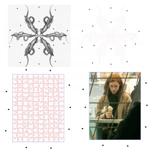
There’s always the option of drawing your puzzle pieces by hand and then tracing them in illustrator or drawing them directly on the computer. Creating them yourself allows you to make unusual shapes and be more creative with the outcome. For a more clean and traditional look there are free sites that will let you put in specifications to automatically generate vectors for a jigsaw puzzle. I’m going to use this one for “Anne Thinking with Ice Cream”
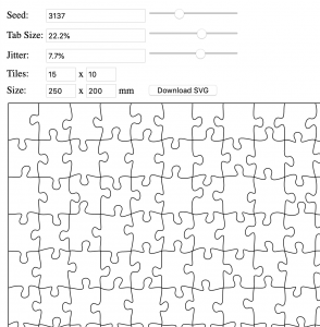
You can mess around with the different settings to find a shape you like for your puzzle pieces, just get the overall size close to the size of your rectangle. Don’t worry if it’s not perfect, since it will create vectors that you can easily adjust the size again in Illustrator, though it may affect the shape of the pieces. When you like the way it looks click “Download SVG” and open the file in illustrator. At this point you can change the strokes around the puzzle pieces to red, and the stroke around the outside of the whole image to blue, so that the inside cuts first to avoid shifting. Don’t use black for any of the strokes, because you will need it later for the registration marks for the camera. Depending what website you use you may have to release or ungroup the resulting vectors in order to edit the lines individually. Once this is done, lay the file over your image and adjust so the rectangles line up.
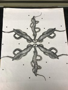
For the irregular shape these square pieces won’t work, so I’ll have to create my own pieces. I’m going to copy a couple sections from the jigsaw puzzle to make it easier. Then I will “puzzle” them in until the shape is fully broken down. The result is more varied, but also more irregularly shaped pieces, and it takes a bit more time than the rectangle. I added a circle to the center of this design to hold the two halves of the puzzle together. Make sure as you compose your file that the strokes are red, blue, or another color recognized by job control that is NOT black, as black should be reserved for the registration marks you will add in the next step.
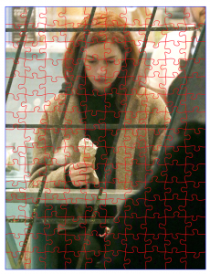
For both of the examples here I thickened the line so it would be visible in the screenshot, but your stroke weights should all be set to 0.01. Once the stroke weights and colors are set, all there is left to do is add the registration marks that show the camera where to cut. They should be black ¼ inch circles surrounding the design. The more detailed or complex the edge, the more points you need. It’s very important that these marks are in the same spot in the image you’re going to print as they are in the file you’ll cut. Lay them on top of each other in illustrator to align the marks perfectly.
Print out the image without the vector lines, so all you have is the picture you want on your puzzle and the registration marks. You can print directly on the material you want to cut or you can print on paper and glue it onto your material with a thin layer of white school glue or regular wood glue, which should be done the night before to ensure it is completely dry. The file you will send to the laser cutter should have the vector lines and registration marks, but not the original image. When you input your power settings set black to “RegMarks.” Make sure that the physical image in the machine is oriented the same way as the file in Job Control, so all the registration marks are situated in approximately the same spot in relation to each other.
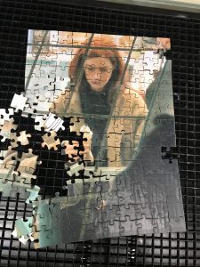
A staff member will help you to attach the Vision camera. Focus the laser as usual, and when you hit “play” in Job Control it will prompt you to find the first registration mark by moving the laser until the camera shows the mark on the screen. Click “ok” and the camera will find the rest of the points automatically and start the cut. If the machine fails to find your reg marks it will tell you there is an error and you can go back to your file and make sure the marks are in the same exact spot on the material and in your file. Each of these took less than 10 minutes to cut, though they’ll take much longer for me to reassemble!